

8/18/2005: Metalwork 6..
I’ve been working on the dents in the nose panel. I always planned on replacing this panel altogether, but i’m surprising myself with how much of the damage I can undo on the existing one.
Still a work-in-progress.. but here’s how it’s going. The tricky part with this panel is getting to the back of it through the limited access holes available. For the most part, I’ve been prying and pushing out the dents, then shrinking them back down with the disc.
|
|
| Before |
|
|
| Before |
|
|
| After |
|
|
| After |
Now i’m at the hard part.. What’s left now are some creases and some shallow dents which can only be corrected by stretching an area back out, which requires getting a dolly behind the area so that it can be worked on-dolly to thin the metal down (stretching it to add area so that the dent rises).
Also there is one rust pitted area and a bunch of really deep scratches (i think someone took a grinder to this panel when it was first bondo’d up) which I can’t do anything about.
8/14/2005: Metalwork 5..
I picked up a cheap ($8) slide hammer and used it to tweak the left tail light opening- the inside edge was slightly pushed in, so the tail light didn’t seat completely flush. It’s amazing how having the right tool for the job can make a huge difference. Smack smack smack and the gap is gone.
|
|
I declared the taillight area basically done and sprayed a little spraycan primer on there for now. This helps the picture somewhat. It’s really quite smooth now, with no filler. Just a few minor low spots, and a little more work required on the corner where the bumper will be.
Also, an update on the opposite side of the car, where I was straightening out a twist where the bumper bolt went through. I got it pretty smooth, so I plug welded the backing plate back on. It came out pretty well, although as expected the heat from welding did cause some shrinking of the metal, which translated into a low spot. I’ve corrected it somewhat, but even if I can’t get it perfect, this area is behind the bumper anyway, so I have to keep a little perspective here.
You may also be able to see that there’s still work to be done o the underside of this panel. Down at the bottom there’s more denting to be smoothed. I didn’t have a good dolly for this high-crown corner though, so I’ll have to get back to that later.
Last night, on a whim, I decided to see how much better I could make the nose panel of the car in-place. I still expect to replace it, but still, it’s educational, so why not see what I can do with it?
So far, I’m pretty impressed with what some crude prying and lots of quality time with the shrinking disc has managed. I’ll post an update on that next time with a before/after.
8/8/2005: Metalwork 4..
So I’m working on the patch panel for the area I cut out of the right side of the car in the last entry. That’s actually going quite well. I’d say that I’ve got the patch looking almost as good as the piece of metal I cut out. Um. Hm. Well, there’s a little more work to go ;-)
The patch was shaped by using a plastic teardrop bossing mallet and a beater bag to stretch the metal in the right areas (obviously there’s only a little stretch/curvature on the right, but a bunch in the flared section on the left. Then I used a chisel-ish post dolly to fine tune the crease line, and a pair of pliers wrapped in duct tape to tip the edge over where it goes into the wheel opening. This was then tucked a bit (using a tucking fork) and flattened.
I’ll describe this process in more detail when I do the next patch. I was still figuring it all out myself, so I didn’t take pictures or anything.
Anyway, there’s still a lot more work to go there to get it perfect, so I decided to do something else instead for a while.
I moved back to working on the left tail light area. This is an area I’ve been working on (on and off) for months. I finally have gotten it about as good as I think I will be able to. After I got the outside surface pretty smooth, I tweaked the light housing mounting surface quite a bit to get it reasonably flat. I think I’m pretty happy with it now, but I’ll probably tweak it a little more after the center rear panel has been fixed.
|
|
OK, well, the difference is impossible to see in these pictures.. trust me though, there should be very little filler this time around.
I’m using the same metalfinishing techniques here as usual. I use a sharpie and a piece of 220 grit sandpaper on a flat board to highlight the low spots, and then use a slapper and dolly to work them up. Then the shrinking disc is used to tighten out anything I overstretch in the process. Much of the art of this is just selecting the right dolly to match the surface you’re working and figuring out how hard to hit it to move the metal without stretching it too much.
I made a lot of mistakes here, but the nice thing about these techniques is that pretty much any mistake can be undone. With enough time and good access to the back of a panel, it can be perfect again no matter what you do to it :)
There was a reinforcing plate behind the panel which I had to remove first before I could straighten the panel. It’s held on with 4 spot welds, which I drilled out.
I didn’t take a “before” photo of this area, but here’s how it looks after being roughed into shape. I basically just pushed out the dent by smacking it from behind with a dolly. Now I have to fine tune it and planish out all the little dents that will remain.
7/17/2005: More metalwork
Here’s the final result for that nose panel I was working on in the last entry. As you can see, the damaged area is pretty hard to see from a distance (you can see it if you zoom in though). I’m happy with the result.
|
|
|
However, what I haven’t photographed is the back of that panel. It’s pretty heavily rust-pitted, so it could be a little thin in places. I’m not positive yet whether or not I want to use it.
I’m actually reporting things a bit out of order. This area of the car was the first one I attempted to fix. I stopped working on it for a bit because I realized how extensive the damage really was.
As you can see in this photograph, there was a crease across the edge of the door and the quarter panel behind it, all the way to the wheel well. In fact, there was also a second crease a few inches above it that is hard to see in this photo.
I used a combination of tools, including a stud welder, hammers, dollies, and the shrinking disc on this area, trying to figure how how to use them. In fact I made many mistakes, including leaving quite a few marks on the metal that I will have to fill later. Still, for the most part, I was able to flatten out the overall surface, at least in the middle.
There’s still a pronounced low spot near the door edge in this photo, and one near the top, and the area near the wheel well (which you can’t really see) is very badly out of shape because I can’t get good access to the back of it.
This may help to visualize what’s going on here. The two yellow lines represent the original, obvious creases in the metal. The red areas indicate the low areas that were created as a side-effect, and which still remain at the time this photo was taken. You can see how the creases must have pulled these other areas inwards and stretched them out of shape.
After doing my best with the rest of the panel (it’s not perfect, but i think a very thin layer of filler will get it there), I finally decided to just bite the bullet and make a big hole in the car for that least damaged area. I couldn’t see any other way to avoid having more than 1/8” of filler in that area to get that sharp edge on the fender flare right. And while I have no objection at all to a think coat of modern filler on my car, a big glob of it would still be shoddy workmanship, and i don’t want it on my car.
|
|
| aigh!! |
So now I’ve crossed some sort of line in this project, I’ve cut a big hole in the car. Now let’s see if I can fill it back in :)
This is going to be a tricky patch to make and to weld in, but it should be a great learning exercise. Once I figure out a few things, I’ll document the process here.
I’m also working on a few other parts of the car at the moment, so I may jump around a bit as I figure out what to do in each case.
7/8/2005: Nose Job
I’ve been working on removing dents and prior damage from several parts of the car. For the most part though, it’s not a very photogenic process. It takes forever, and improvement is very slow. But it really is an interesting process, and i’m slowly getting better at it. I figured i’d share the basics by doing a writeup on one part of the car, the upper nose panel.
It seems that these cars often get smacked in the nose at some point in their lives.. It seems like all the parts cars I see are in similar condition. However, while my car has damage spread across most of the nose, the parts car’s damage is more localized and was previously repaired reasonably well.
|
|
To get a better look at it, I cut the nose section out of my parts car and drilled and ground out all of the spot welds to remove the outer skin from the inner structure.
This skin is indeed somewhat dented in one area, but overall it’s definitely in better shape than the one that is on the car. So i decided to go ahead and try to straighten out the dents.
I’m not yet sure if i’ll actually use this panel as a patch for my car, but I think that if i can get it straightened out, i may use it to replace the more extensively dented piece that’s on my car. Unfortunately this panel is a little rusty on the back side, so i will have to see how thin it ends up being when this rust is fully cleaned out.
I used a large, low crown dolly and a slapper to raise the larger overall low area of the dented area, then used the shrinking disc to level it a bit (more on this later).
After repeating this process several times, the surface started to resemble the right curve, but there are a bunch of small dimples left over from the prior repair that was done on this car.
|
|
|
To smooth these out, i need some way to planish the panel. Planishing is basically just smoothing a panel by using repeated small hammer blows (or something like an english wheel, but I don’t have one)
Since I don’t have an air-powered planishing hammer or english wheel, I’ll use the low-cost manual alternative, a post dolly:
A post dolly is really just a hard smooth die that’s clamped in place (on a post, or whatever). You hold the panel over this and tap out the imperfections in the panel by hitting the die with a smooth hammer or slapper.
The same basic principles apply as when using a regular hand-held hammer dolly. When you work the metal “on-dolly”, the steel effectively being smashed between two hard surfaces, and so it stretches.
If you work the metal “off-dolly”, (that is, the dolly is under the low spot and you only hit the high spots with the hammer), this stretching effect is minimized, because the low spot is pushed up, in effect shrinking the trapped metal somewhat by forcing it together as it’s rearranged.
The die i’m using (clamped in a vise) is actually one of the ends from this hammer kit. I don’t find this hammer all that useful, but the ends are pretty good for this use.
I ground the sharp edges off the hammer end (you never want a sharp edge on a hammer- one false move and it will dig into the metal and leave a mark) and clamped it in the vise. I then mounted a cheap laser pointer to my ceiling above the vise and wired in a remote switch so that i can easily turn it on and off. (ideally, i’d have this hooked to a foot pedal, but i didn’t have one to use, so for now it’s just a microswitch i can nudge with a hand or knee.)
To allow for adjustment, I screwed a piece of metal to my ceiling, and mounted the laser pointer to a magnet. This works really well, actually.
|
|
|
||||||
|
|
So, to raise small low areas in the panel, i point the laser at the center of the crown of the dolly, then put the panel in place and line up the laser dot with the low spot. Then when i hit the panel with a hammer or slapper, i know that it’s centered on the low spot, so that’s what will be planished out.
If I hit too hard, it stretches the metal a bit, making a larger high spot in place of the small low spot. This is in fact what happened, but it’s not a problem to fix.
Once I’ve raised most of the low spots, i then reapply the sharpie and sand to get a look at things. As you can see, the low spots are reduced, but there’s one big high area now.
To shrink this stretched metal down and lower this high area, I use the shrinking disc. This selectively heats up the high spots. When it’s cooled off back to room temperature (you can use water or compressed air to speed this cooling), the metal shrinks slightly beyond its initial shape.
Here’s the result of that:
As you can see, it’s starting to level out now. There are some low spots remaining near the edges of the panel.
Basically, by repeating the steps above over and over, i can refine the surface until all the dents are essentially gone. There are still going to be some rust pits and scrapes on the surface which I can’t eliminate, but those can always be filled later if I do decide to use this panel.
For more information on the techniques I am using, see metalmeet.com, and in particular this tutorial.
Some of the tools I am using, and where I got them:
- Shrinking Disc - Wray
Schelin
These are available from several other sources. It’s just a flat stanless steel disc with a lip on the edge and a dimple in the middle, so several folks make them. Espect to spend about $50 on them. A very inexpensive 9” grinder is available from Harbor Freight that works fine with these discs. I use a 7” rubber backing plate from home depot or similar and a 9” phenolic backing bad behind the plate to provide support. - 7 pc. Hammer/Dolly Set - Martin Tools
I really like this set of hammers and dollies. They are *MUCH* harder and better polished than the cheapie chinese sets you can find at harbor freight (and everywhere else). I found that sears’s web store had a good price on this set (here). - Slapper
A slapper can be used like a broad hammer to spread out a blow over a larger area. This works great for raising small dents, because you’re effectively hitting simultaneously all the way around the outside of the dent when you hit it with a slapper. Slappers can be made from a car’s leaf spring, bent into proper shape and polished. Since I don’t have a torch (or a leaf spring), i instead bought one from autobodystore. A light slapper also comes with the martin tool set, which is good for fine work, but not really heavy enough for a lot of the stuff i’m doing. - 3M Roloc Discs
I use the 2” discs on an angle die grinder for general cleanup of metal parts, stripping paint and rust, etc. I also use the roloc bristle brush and sandpaper for some tasks. - Random-Orbit or D/A Sander
Ideally i’d use an air-driven D/A sander for final metal surface preparation and light paint removal, but I find that my little compressor can’t put out enough air to drive one. So for now i’m using a dewalt electric sander for this kind of thing. - Markers/Flat Sanding Block
I’m just using a bit of relatively-flat plywood with a piece of 220 grit “stickit” style sandpaper on it. I’m just copying what Wray Schelin uses, and it seems to work well for me. As he said in a metalmeet post:I have tried Dykem, and many other highlighters. The best by far is a Magnum Magic marker. These are monster sized markers.
When I wrote that original article about taking dents out at that time I used a file to skate across the metal to highlight the highs and lows. I no longer use a file. I use stickit 220 or 150 sandpaper on a 6 inch round by3/8” thick disc of baltic birch plywood. For large low crown panels I use a 2.5” wide x 16” piece of 3/8” aluminum with a boardfile 150 or 220 stickit paper.
6/28/2005: Half-a-Car Comes Home
As I’ve mentioned before, many years ago my father got a parts car and stored it in our barn. The deal included a number of new or rebuilt parts, many of which I will be using in this restoration.
However, the requirement was that we also take the car itself, which had basically rusted itself in half over the years of being left outside, unprotected. In order to haul it home, my dad cut it the rest of the way in half, and so it has been stored in two halves in the barn ever since.
I decided to bring the front half of the car to my house so that I could get a better look at it and see if it could contribute any sheetmetal to the repair of the front of my car.
My mom and I loaded it into the back of my truck. It barely fit, but i couldn’t close the tailgate behind it, so folks driving behind me would have seen the dashboard and steering wheel apparently hanging off the back of a pickup. I imagine that was a fairly surprising sight :)
After getting it home and not dropping it on I-84, I decided that I needed some sort of a dolly to load it on, so that I could easily move it around my garage without assistance and without scraping up my garage floor.
I screwed together a few 2x4s and some scrap wood I had laying around and bought 4 caster wheels and bolted them on. The result worked out to be almost the same height as the back of my truck (by luck more than design), and I was able to slide the car off the back of the truck and onto this dolly by myself. I figured “Hey, what’s the worst that can happen? I drop it on the driveway? So what?”
It worked out great! After bolting the body down to it so it won’t slide off, I can easily roll the thing around with one hand, in and out of the garage.
Here’s what by garage now looks like. I’ve christened serial number 40912 Eric the Half-a-Car :)
Even if it wasn’t half a car, it would still be beyond saving. The rust throughout the inner structural parts is amazing, once you look closely. The wiring is terrifying, having been spliced and hacked on for years.
But it’s still useful to me, for reference, for a number of little parts, and to confirm what’s “normal” for a fiat 1500 cabriolet tipo 118K.
Unfortunately the front sheetmetal isn’t perfect.. It looked pretty good until I stripped off some paint- there’s some prior damage and a fair amount of filler in the nose area and under the headlight on one side. But some areas are definitely in better shape than on my car, so it may still provide some pieces, or at least templates.
6/4/2005: Bodywork Plans
You know, it annoys me when people don’t post any updates to their sites for months at a time, and here I go doing it myself! I have no real excuse, either..
The main reason I haven’t put any posts together is that i haven’t done anything particularly photogenic in a while.
I have mostly been doing research and planning (and buying parts). Let me review where things stand now:
- The car has been disassembled, and I believe i’ve identified all the major areas work that will need to be done.
- Rocker panels (structural and outer) replaced.
- The replacement front subframe is ready to be assembled, and will then be stored until the body work is complete.
- All of the engine ancillaries have either been rebuilt or will be replaced.
- I’ve been buying new and used parts from a variety of sources as they turn up.. I’ve got parts from all over the country and all over the world. In some cases i have 2 or more of a given part, and will choose the best ones when I get to that part of the car.
Although there are some more mechanical parts i can finish up work on (such as completing the suspension reassembly and restoring a few more engine bits), i’ve decided to switch focus for a while to the bodywork. Getting the body shell into shape will get me closer to being able to start putting pieces back onto the car, which I think will a real relief.
There is quite a bit of body repair that will be needed on this car. At this point, the rust is not widespread. There are a few small spots that will need to be patched, but mainly the rust is only in the floor.
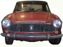
Before I worry about the rust though, i would like to fix the larger dents. This car was in an accident (or two) back before my father got it, probably in the 70s or early 80s. The worst damage is to the front of the car:
|
|
|
|
These panels are badly damaged enough that they will need to be replaced. I have access to a few parts cars, or can attempt to fabricate new panels if necessary.
The back of the car also has some damage, and will require replacement of the rear panel between the bumper and trunk lip to meet my standards.
My goal is to metalfinish the car to the point where a less than 1/16 inch of filler is required to get everything smooth. While it is possible, given enough time and skill, to get the car to the point of needing little or no filler, i’ve decided that a small amount of filler is going to be acceptable to me. When these cars were originally made, pininfarina used a lot lead and some filler in them, so i don’t need to knock myself out trying to get it better than original.
I’ve spent a lot of time over the last year or so researching welding, panel forming, and dent repair. One of the best resources has been the forum at metalmeet.com. It’s full of tutorials and expert advice, and i read it daily now.
I also attended a 3-day class tought by Wray Schelin and Dutch Comstock, two of the main personalities on the site. This was really really helpful in helping me to really understand how to make metal move the way it needed to move, and foremost in helping me to not be afraid to bang on a piece of sheetmetal. It’s remarkably forgiving, if you know how. Anything you can do can be reversed using the right techniques.
I’ll be covering my first attempts at dent repair on the car in the a future article.
1/16/2005: A New Year, a Little Progress
I’m sorry I haven’t posted an update in a while.
Cold temperatures, family obligations, and various other real-life distractions have kept me occupied. And inertia is also a big factor.
I find it’s really important for me to make myself go down there and do _something_ every day, even if it’s just straightening up.
Here’s a short list of things I’ve done recently..
- painted disc brake shields, wheel hubs
- cleaned, wire brushed, and painted the oil condenser
- Took off the turn signal assembly
- started to clean the wiring harness. relabeled and checked everything against the wiring diagrams.
- painted the water pump pulley and clutch with rust encapsulator and under-hood black
- had the pulley pressed onto the NOS water pump I bought on ebay (from portugal!).
- Reassembled the fan clutch, with a new brush, replated hardware, etc.
At the moment I’m cleaning up the fan, so I can assemble the water pump completely and set it aside. I’m also going to assemble the front suspension, now that everything’s painted, so I can store that as well.
1/16/2005: Water Pump Finished
As I mentioned a while back, I am replacing the water pump on my car with a NOS one I purchased on ebay. The pump came “bare” and needed to have the pulley from one of my other pumps pressed onto it.
Here’s the result:
I’m pretty happy with how it came out. It took me a few tries to get the fan to look good. I ended up sanding it with 320, 400, 600, 1000, and 2000 grit sandpaper to take out the scratches. At each level, I would sand (wet) in straight lines, in both directions.
Then I buffed it very lightly with a string wheel and plastic polish on my bench grinder. Pushing too hard on this soft plastic can very easily melt it, and I did have to redo a few spots until I got the right feel for it.
My overall goal wasn’t to make this fan translucent or extremely shiny, just to remove the deep scratches and make it look clean. I think it came out well.
The metal parts were re-plated, and came out pretty looking decent. The plater left a protective coating on the parts that gave them a slightly powdery appearance. On large parts like these rings, I found that a very light application of metal polish takes that off and shines them up. (Hopefully without taking any of the cadmium off)
You can see some pitting on the outer ring.. I probably could have prepared that part better before plating, but it’s fine.
When I originally disassembled these water pumps I used an air chisel with a blunt tip to losen the large nut on the end of the pulley. While this works fine, it does damage the nut slightly. For reassembling it, I decided to try to make a wrench to fit it.
I got this idea from Kerry Chesbro’s site. It appears that ferrari used an identical nut to hold on the steering wheel hub. Kerry ground down a regular socket to make something that would fit:
I liked the idea, so I made my own. I used a cut-off wheel on my grinder and my dremel. It took a bit of trial and error, but what I found worked best was to use the original points on the 6-point socket as centering marks for the 6 tabs that needed to be left. So here’s my final socket.. it worked great.
If anyone would like to borrow it, just drop me an email and i’ll send it to you.
The next projects on my agenda are to finish up cleaning the wiring harness and reassembling the new front suspension.
12/08/2004: Steering wheel
Bought a steering wheel puller and took off the steering wheel hub today.
I got nothing meaningful accomplished today, but I took two photographs that lined up so well that I couldn’t resist.
12/05/2004: Painted Brake Rotor
As I mentioned last time, I’ve got one good brake rotor and two good hubs (with new bearings).
I painted the brake rotor and one hub in satin black with VHT high-temperature paint, being careful to mask off all the machined sufaces.
I cured the paint in the oven, and it looks good. (well, as good as an old rusty rotor can be expected to look ;-)
|
|
|
All reassembed (with anti-seize so I can get it apart again in the future!). Now I just need to find another one for the other side of the car..
12/02/2004: Suspension, Brakes
Over the last month or so, i’ve been reassembling the new subframe for my car.
Some time ago, I put together a page of photos and diagrams of the front suspension for reference. This has been quite useful in determining what colors to paint things and how to reassemble all the parts. Here’s a link for the curious.
Here’s what the trunnion looks like disassembled:
Each end cap is threaded on the inside and the outside. The outer thread screws into threaded openings in the control arms. These are tightened down and do not move. the inner thread engages the threaded shafts on the trunnion, and are lubricated so that the trunnion can rotate along that axis. The two rubber boots are just to help keep the threads greased and keep the dirt off them. Note that although there is a grease fitting on only one side, there’s an internal passage all the way through to the other side, with an opening to the center bushing to lubricate the steering knuckle shaft.
Installing these things is a trick, since you’re simultaneously engaging two sets of threads. In one case (the top one on the right side), I think perhaps the control arm was slightly bent, such that the two sets of threads weren’t in sync completely. It was very hard to get the thing together, but eventually I did get it on. In general, you want to get one side tightened until it just starts to engage, then start the other side, then tighten both a little at a time. I added some loctite on the outer threads to try to keep them from loosening up.
|
|
Once tightened down, the rubber boots get pinched against the trunnion bodies, and everything seems quite tight. I think once the car is on the road though, things will break in and start to move more easily.
Note that the trunnion end caps were silver cad plated and the control arms and other suspension is painted with POR-15.
I also test-fit one of the steering knuckles:
I have a total of 6 rotors. 2 on the car now, the 2 blue ones that were originally on this subframe, and 2 other old rusty ones. I wanted to get two of them turned down to remove some of the rust pitting and go with those, but before I could do that, state law here requires that they not be turned below the minimum thickness as defined by the manufacturer. Normally, this is stamped into the rotor itself, but FIAT didn’t do that, which made things complicated. It also turns out that no minimum thickness was documented in either of the service manuals I had (the 118H and the 118K one), or anywhere else I could find.
I asked about this on the fiatcabrios list, and nobody knew for sure either. Ron Horowitz had a sedan rotor though, and measured it at .375”, and felt that the cabrio ones were probably the same. The (probably conservative) spec from fiat is that they can be turned .020” under, which means I should shoot for .350”.
I took my two thickest ones to a local shop and had them turned. One of them cleaned up pretty well and came in right at .350”. The one on the right is really no good though- as you can see, it would be necessary to take even more material off to clean it up, and it’s already thinner than I want.
|
|
|
|
All the others I have are thinner than .350”, so I am currently looking for another decent used rotor. Unfortunately new ones are VERY hard to come from, and the rotors appear to be unique to the 1500 cabriolet, which means it’s unlikely that they’re being widely reproduced.
If necessary, Chris Obert can supply them as a special order item, but they don’t come cheap. So i’m hoping to find a used one in comparable condition that I can work with. I’m not willing to put an unsafe brake rotor on my car, that’s for sure. It’s not worth risking your life to save a few bucks!
I’ve done some googling around, and so far i haven’t found any sources for this rotor (or even one close enough to it to adapt), but i’m sure it can be done if I get really desperate. Unfortunately, FIAT used a different size center hole on these cars than on any of the later cars (which almost all use identical rotors)
The blue discs, while too thin to use, had brand new bearings and races in them, so i’ve separated the hubs from the discs and will be mixing and matching the best of each. I probably should have done this before I had the rotors turned, but oh well..
Separating the rotor from the hub is pretty hard.. What worked best for me was to first clean up any rust and buildup around where the hub comes through the face of the rotor with a 3M surface conditioning disc. Then I screwed in 4 lug bolts and placed the bottom of the rotor surface on a pair of 2x4s to support it. I hammered on the 4 bolts (going corner to corner) until it started to move, then switched to hammering against a wood block placed on the center section until it came apart. I separated 3 of the 4 ones I had (which weren’t on the car) this way. On the last one (the rough one pictured above), the bolt that holds the rotor to the hub was starting to round off, so I decided to just leave it.
For paint, i’m planning to use a high-temperature matte black paint. I think originally, these would have been bare (rusty) metal, but I think black will probably look better. I’ll do the calipers in a cast iron colored paint later.
10/16/2004: Wiring Harness
Tonight I finally finished removing the wiring harness from the car. This was a tedious process and involved taking LOTS of pictures and labeling lots of little wires.
I believe that pulling out the front harness altogether was the right thing to do for this car. It’s really a fairly simple electrical system compared to more modern cars, but it is old, and most of the connections are corroded and need some TLC. Having it out of the car will give me a lot of flexibility to fix it properly. I can take it indoors on cold days and clean and replace ends on the wires, rather than having to work under the dashboard of the car like a contortionist.
Also, having the wiring out of the car will make stripping and repainting the car a lot easier, when the time comes.
Hopefully I took enough photos to get it all back together properly!
10/2/2004: Water Pump
Since I have several spares, I decided to disassemble and inspect the water pump on my car to decide if I needed to do anything to it.
I looked at 3 water pumps and managed to basically destroy two of them in the process (one of which already had a frozen bearing, so i don’t really count that ;-)
Here are the results of my analysis..
These pumps appear to come in two main types. You can tell them apart by looking at the fan belt pullies. “Type 1” has basically flat edges, and “Type 2” has a lip that curves up at the edge. Here’s a comparison photo. Type 1 is on the left, 2 is on the right.
What i’ll call “type 1” has a heavy cast fan belt pulley and 3 slot-headed screws holding on the back plate. These are very hard to remove. It seems very likely that at least one of them will snap in the process, requiring you to drill it out (not very easy to do when you’re trying to drill out (hard) steel that’s surrounded by soft aluminum!
|
|
| backing plate bolts and one screw |
In my case, I had one of these that had been soaked in grease early in its life, and so had very little rust- the bolts came out easily, allowing easy access to the back plate. After destroying another pump, though, I learned that attempting to remove either the impeller or the (type 2) fan belt pulley is a bad idea. It’s likely that they will bend or snap, and turn the pump into scrap.
Conclusions
With my skill level at least, the pump seals and bearings (the parts that would fail) are really not servicable on these pumps. The only way they could be gotten at would involve a lot of heating with a torch, which would probably destroy the old bearing and seal anyway. So unless you’re really desperate, it’s probably better to try to find another used (or new) water pump than to try to rebuild one yourself at this point.
What you can do pretty safely is to rebuild the fan clutch assembly and replace the rear gasket (behind the plate). However, if you do opt to take off the plate, bear in mind that the screws could snap, and you could have to drill them out- try to avoid that by using tons of penetrating oil and patience.
I did succeessfully remove the fan pulley on a type 1 water pump, but this wasn’t really all that helpful in the end- I wasn’t able to remove the lock screw that holds the main pump bearing in place, nor was I able to remove the impeller. So I recommend just leaving the fan pulley in place.
Rebuilding The Fan Clutch
Here’s the basic procedure for tearing down the fan clutch portion of the water pump, that is, everything forward of the belt pulley.
- Remove the three nuts that hold on the plastic fan blades and outer ring.
- Pull off the fan
- Remove the 3 bolts and 3 adjusting studs that hold on the center ring, remove it, and set aside.
- bend down lock tabs on the center bolt.
- Using a rubber strap wrench to hold the fan pulley steady
- Use an air chisel to loosen the center nut. I found this to be very effective, but it will deform the nut slightly. If you have a better tool for this, by all means use it.
- Once the nut is loose, use channel locks to take it the rest of the way off.
- Using a 3-jawed gear puller, pull off the fan pulley, on its bearing It may even pull off without the need for a puller.
That’s about as far as I have gotten at this point. Once I start to reassemble the water pump, I will write another entry about how to inspect the electromagnets, the brush, and to adjust the fan clutch after assembly.
Detailing
Based on the three pumps i’ve inspected (especially one that was well-preserved by oil and grease), here are what I believe to be the proper finishes for the various steel parts of the pump:| Component | Photo | Finish |
|---|---|---|
| outer ring | silver cad | |
| inner ring | silver cad | |
| ring studs |
|
? |
| ring nuts | silver cad | |
| inner ring bolts | black oxide? | |
| inner ring adjusting studs | ? | |
| center nut |
|
black oxide? |
| center lock washer | silver cadmium | |
| pulley |
|
flat black |
9/8/2004: Door Disassembly
Over the last few weeks i’ve been taking apart the doors. I removed the windows, weatherstrips, etc.
Tonight I took a try at getting the right side door to align better. This required drilling out a number of rivets and removing an access panel. Then you can loosen up the hinge bolts and try to realign the door. I didn’t succeed completely, but I think i made some improvement.
I’ll need to get back to that later and make another attempt at it. I didn’t take any photos off the process, but I’ll take some next time I am in there.
7/31/2004: Quick Update
Just poking my head in here with a quick update. In the last few weeks, i’ve been working on a few projects.
First, I cut out the bottom of the battery box, which was badly rusted, and am currently figuring out how I want to go about fabricating a replacement.
Then, last night I got ambitious and took off the windshield. It’s amazing how much of this tarrish goop they used to seal the bottom gasket to the body. There was at least 1/4” everywhere.
This afternoon I decided what the heck, and started to work on pulling out the wiring harness. This is tricky business, requiring lots of photographs and labelling. It’s pretty scary, but it’s really for the best. This way I can go over the whole thing and replace any bad connectors or wires with fresh ones. It also will be necessary to get these out of the way if I have the car’s paint stripped by media or soda blasting, and will simplify things with painting. There’s really not much reason not to strip the car down to a bare shell at this point- there’s so little left on it anyway.
I’ll post more detailed info on the battery box project as it proceeds, and i’ll get some photos of the windshield-less car up here soon as well.
7/11/2004: Carb Rebuild
Although my car is a 1966, it has an engine from an earlier 118H car. I am going to keep this engine in the car, even though it’s not technically correct.
One of the differences is that it has this older, simpler carburetor, the Weber 28/36 DCD. Rebuilding it was a very satisfying project.
I mostly followed the process outlined in the Haynes Weber Carburetors book. The FIAT 118H Service Manual was also very helpful, since it had nice photos of the fiat-specific linkage, and contained tables with the specific jetting and float settings for this car.
First, the pictures:
|
|
| Before |
|
|
| After |
So cool. Here’s a photo essay of the rebuilding process:
|
|
|
|
|
|
|
|
|
|
|
|
7/9/2004: Reassembling the Generator
Today I reassembled the generator, which i’d taken apart and painted a while ago. This was straightforward except for one thing. I’m replacing the original front ball bearing bearing with a new sealed bearing (for reference, this is a standard # 6302 ball bearing, with a 15mm ID, 42mm OD, 13mm Wide). It’s an interference fit in the front housing of the generator, so it needed some persuasion to install it.
I chilled the bearing in my freezer, on the off chance it would make it shrink a bit (no idea if it made any difference). Then I used two sockets to tap it into place, as illustrated below.
Then the rest of it went together pretty easily. I replaced all the screws and nuts with new ones while I was in there.
Deciding what color to paint the body of the generator was kind of interesting. Looking at the illustrations in the original service manuals wasn’t that helpful:
|
|
It appears that the generator could be either black or some lighter color. I decided to go with an unpainted metal appearance, as I could find no traces of paint on any of the generators I looked at. I could also have painted it black. I’ve seen some done that way. It’s hard to be sure what’s “right” for this kind of thing. I think it will look fine either way, so I decided to go with the left-hand appearance, with the generator and starter being different colors.
Well anyway, that’s one more part done and on the shelf, waiting to go back on the engine down the road. Next comes the carburetor!
7/8/2004: The car’s home!
This week’s exciting news is that the rocker panels are done and the car has come home. The inner and outer panels have been fabricated and welded in.
Last week I finally got around to sending out a box of nuts, bolts, and hardware for cadmium plating. I’ll post more information on this when I get them back.
I’ve got plenty of projects to work on now. The front suspension of course still needs a bit more work. The generator is all cleaned up and painted, and I’ll be assembling that as soon as I have the new bearing pressed in. I’ll post pictures of that process.
I’ve also got a rebuild kit for the carburetor, so I can do that as well. I’m trying to rebuild all these little accessory parts on the engine while i’m working on the body of the car. My plan is to then start getting into rebuilding the engine itself while the car is away being painted. That’s still quite a way of, of course, so my priorities could easily shift.
6/16/2004: Rocker Panel Update
Today I stopped by the shop that is rebuilding the rockers and snapped some photos. The driver’s side is largely done, and they’re about to start on the passenger’s side rocker. It’s been all opened up and trimmed in preparation for the inner patch panel.
I’ll probably also have them patch the holes in the wheel arches which open into the rocker area. The remaining rust on the car is on separate or non-visible panels, and i’ll take a shot at fixing it myself.
Here are the photos:
|
|
| Trimmed back, awaiting patches |
|
|
| (almost) Finished Panel |
|
|
| Front Edge |
It’s pretty exciting to start seeing visible improvement in the appearance of the car :)