

10/27/2004: This made my day
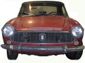
This car belongs to Gene Phillips. He sent a series of photos to the fiatcabrios list.
This car started life as a ‘66 cabriolet and was transformed by its prior owner into this monster.. It’s built on a custom tube chassis with roll cage, custom suspension, 383 stroker motor and a powerglide.. you name it, it’s there.
As Gene said, “I know it kills the purist in you guys, but it is really unique.”.
Heh, I think it’s great. If you’re going to chop up a “classic”, you might as well go all the way. This car is magificently over the top.
I can safely say I won’t be doing anything like this to my car, though :)
10/19/2004: Catching up..
I’ve been very busy lately, and haven’t gotten as much done on the car as I’d like. I also haven’t posted much to this site in about 2 months, even though I have accomplished a few things on the car.
One thing I’ve certainly seen as i’ve read other folks sites on their car restoration projects is that this sort of lull is not unusual.. Life gets in the way sometimes, and motivation comes and goes as well.
Well, today I posted 3 other entries that catch things mostly up to where I am as of now.
No guarantees, and no deadlines, but I do hope to pick up the pace a bit on the car. At this point the car is almost completely down to a bare tub. I have plenty of body work to do and components to restore. So there’s certainly no shortage of things to keep me busy. Cold weather’s coming, but I’ll try not to let that slow me down. We’ll see what happens.
10/16/2004: Wiring Harness
Tonight I finally finished removing the wiring harness from the car. This was a tedious process and involved taking LOTS of pictures and labeling lots of little wires.
I believe that pulling out the front harness altogether was the right thing to do for this car. It’s really a fairly simple electrical system compared to more modern cars, but it is old, and most of the connections are corroded and need some TLC. Having it out of the car will give me a lot of flexibility to fix it properly. I can take it indoors on cold days and clean and replace ends on the wires, rather than having to work under the dashboard of the car like a contortionist.
Also, having the wiring out of the car will make stripping and repainting the car a lot easier, when the time comes.
Hopefully I took enough photos to get it all back together properly!
10/2/2004: Water Pump
Since I have several spares, I decided to disassemble and inspect the water pump on my car to decide if I needed to do anything to it.
I looked at 3 water pumps and managed to basically destroy two of them in the process (one of which already had a frozen bearing, so i don’t really count that ;-)
Here are the results of my analysis..
These pumps appear to come in two main types. You can tell them apart by looking at the fan belt pullies. “Type 1” has basically flat edges, and “Type 2” has a lip that curves up at the edge. Here’s a comparison photo. Type 1 is on the left, 2 is on the right.
What i’ll call “type 1” has a heavy cast fan belt pulley and 3 slot-headed screws holding on the back plate. These are very hard to remove. It seems very likely that at least one of them will snap in the process, requiring you to drill it out (not very easy to do when you’re trying to drill out (hard) steel that’s surrounded by soft aluminum!
|
|
| backing plate bolts and one screw |
In my case, I had one of these that had been soaked in grease early in its life, and so had very little rust- the bolts came out easily, allowing easy access to the back plate. After destroying another pump, though, I learned that attempting to remove either the impeller or the (type 2) fan belt pulley is a bad idea. It’s likely that they will bend or snap, and turn the pump into scrap.
Conclusions
With my skill level at least, the pump seals and bearings (the parts that would fail) are really not servicable on these pumps. The only way they could be gotten at would involve a lot of heating with a torch, which would probably destroy the old bearing and seal anyway. So unless you’re really desperate, it’s probably better to try to find another used (or new) water pump than to try to rebuild one yourself at this point.
What you can do pretty safely is to rebuild the fan clutch assembly and replace the rear gasket (behind the plate). However, if you do opt to take off the plate, bear in mind that the screws could snap, and you could have to drill them out- try to avoid that by using tons of penetrating oil and patience.
I did succeessfully remove the fan pulley on a type 1 water pump, but this wasn’t really all that helpful in the end- I wasn’t able to remove the lock screw that holds the main pump bearing in place, nor was I able to remove the impeller. So I recommend just leaving the fan pulley in place.
Rebuilding The Fan Clutch
Here’s the basic procedure for tearing down the fan clutch portion of the water pump, that is, everything forward of the belt pulley.
- Remove the three nuts that hold on the plastic fan blades and outer ring.
- Pull off the fan
- Remove the 3 bolts and 3 adjusting studs that hold on the center ring, remove it, and set aside.
- bend down lock tabs on the center bolt.
- Using a rubber strap wrench to hold the fan pulley steady
- Use an air chisel to loosen the center nut. I found this to be very effective, but it will deform the nut slightly. If you have a better tool for this, by all means use it.
- Once the nut is loose, use channel locks to take it the rest of the way off.
- Using a 3-jawed gear puller, pull off the fan pulley, on its bearing It may even pull off without the need for a puller.
That’s about as far as I have gotten at this point. Once I start to reassemble the water pump, I will write another entry about how to inspect the electromagnets, the brush, and to adjust the fan clutch after assembly.
Detailing
Based on the three pumps i’ve inspected (especially one that was well-preserved by oil and grease), here are what I believe to be the proper finishes for the various steel parts of the pump:| Component | Photo | Finish |
|---|---|---|
| outer ring | silver cad | |
| inner ring | silver cad | |
| ring studs |
|
? |
| ring nuts | silver cad | |
| inner ring bolts | black oxide? | |
| inner ring adjusting studs | ? | |
| center nut |
|
black oxide? |
| center lock washer | silver cadmium | |
| pulley |
|
flat black |
9/8/2004: Door Disassembly
Over the last few weeks i’ve been taking apart the doors. I removed the windows, weatherstrips, etc.
Tonight I took a try at getting the right side door to align better. This required drilling out a number of rivets and removing an access panel. Then you can loosen up the hinge bolts and try to realign the door. I didn’t succeed completely, but I think i made some improvement.
I’ll need to get back to that later and make another attempt at it. I didn’t take any photos off the process, but I’ll take some next time I am in there.
8/25/2004: Photo Gallery
A while back, I set up a photo gallery on this site for other folks to use. I’m not putting my own pictures in it for the most part, since I have so many and my disk space on this web site is limited. But here it is.. Anyone is welcome to share fiat-related photos here. Just request an account, create an album, and upload away.
This should be a lot more flexible than the fiatcabrios yahoo group’s photo gallery, and it will preserve the photos’ full resolution.
8/17/2004: Concorso Italiano 2004
Last week I went out to Monterey, CA to attend some of the many car-related events during the “monterey car weekend”. (in fact, it covers the better part of a week at this point).
I ended up spending thursday with a bunch of Fiat America folks, on a cleverly organized “frugal thursday” tour of various events which can be gotten into for free, including the warm-up day for the Monterey Historic Races at Laguna Seca.
On friday, I went to the Concorso Italiano event. It was really a great time! There were a mind boggling number of expensive italian cars there. I didn’t take a whole lot of photos of those, but here are some links to other peoples’ collections:
- pelicanparts.com (1000+ photos)
- broadsword.com (27 photos)
- supercarfreak.net (630 photos)
- dealerrater.com (567 photos)
- michaelp.org
![[New]](http://www.hitchhiker.org/fiat/images/new.gif)
I got to meet Tim Schlose and Dan Lennon, who both brought ‘65-66 (118K) 1500 Cabriolets. I filled most of my camera’s memory card with just close-up pics of these two cars, which will come in handy for reference.
|
|
| Tim Schlose’s 1500, 118K 047086 |
|
|
| Dan Lennon’s 1500, 118K 044778 |
Great cars, guys! Makes me anxious to get back to work on mine :)
Tim’s car is very pretty, with a great body and a mildly customized interior. It’s been switched to cloth upholstery, and he’s added a few OSCA-inspired touches, like the nardi wheel and footrest:
Dan’s is fairly original overall- most of the car seems untouched, which is great as far as I am concerned! The car is amazingly solid and rust free, even the undercarriage. Check out that grille!
Hard to believe the pitted one on my car is supposed to look that smooth :)
7/31/2004: Quick Update
Just poking my head in here with a quick update. In the last few weeks, i’ve been working on a few projects.
First, I cut out the bottom of the battery box, which was badly rusted, and am currently figuring out how I want to go about fabricating a replacement.
Then, last night I got ambitious and took off the windshield. It’s amazing how much of this tarrish goop they used to seal the bottom gasket to the body. There was at least 1/4” everywhere.
This afternoon I decided what the heck, and started to work on pulling out the wiring harness. This is tricky business, requiring lots of photographs and labelling. It’s pretty scary, but it’s really for the best. This way I can go over the whole thing and replace any bad connectors or wires with fresh ones. It also will be necessary to get these out of the way if I have the car’s paint stripped by media or soda blasting, and will simplify things with painting. There’s really not much reason not to strip the car down to a bare shell at this point- there’s so little left on it anyway.
I’ll post more detailed info on the battery box project as it proceeds, and i’ll get some photos of the windshield-less car up here soon as well.
7/11/2004: Carb Rebuild
Although my car is a 1966, it has an engine from an earlier 118H car. I am going to keep this engine in the car, even though it’s not technically correct.
One of the differences is that it has this older, simpler carburetor, the Weber 28/36 DCD. Rebuilding it was a very satisfying project.
I mostly followed the process outlined in the Haynes Weber Carburetors book. The FIAT 118H Service Manual was also very helpful, since it had nice photos of the fiat-specific linkage, and contained tables with the specific jetting and float settings for this car.
First, the pictures:
|
|
| Before |
|
|
| After |
So cool. Here’s a photo essay of the rebuilding process:
|
|
|
|
|
|
|
|
|
|
|
|
7/9/2004: Reassembling the Generator
Today I reassembled the generator, which i’d taken apart and painted a while ago. This was straightforward except for one thing. I’m replacing the original front ball bearing bearing with a new sealed bearing (for reference, this is a standard # 6302 ball bearing, with a 15mm ID, 42mm OD, 13mm Wide). It’s an interference fit in the front housing of the generator, so it needed some persuasion to install it.
I chilled the bearing in my freezer, on the off chance it would make it shrink a bit (no idea if it made any difference). Then I used two sockets to tap it into place, as illustrated below.
Then the rest of it went together pretty easily. I replaced all the screws and nuts with new ones while I was in there.
Deciding what color to paint the body of the generator was kind of interesting. Looking at the illustrations in the original service manuals wasn’t that helpful:
|
|
It appears that the generator could be either black or some lighter color. I decided to go with an unpainted metal appearance, as I could find no traces of paint on any of the generators I looked at. I could also have painted it black. I’ve seen some done that way. It’s hard to be sure what’s “right” for this kind of thing. I think it will look fine either way, so I decided to go with the left-hand appearance, with the generator and starter being different colors.
Well anyway, that’s one more part done and on the shelf, waiting to go back on the engine down the road. Next comes the carburetor!
7/8/2004: The car’s home!
This week’s exciting news is that the rocker panels are done and the car has come home. The inner and outer panels have been fabricated and welded in.
Last week I finally got around to sending out a box of nuts, bolts, and hardware for cadmium plating. I’ll post more information on this when I get them back.
I’ve got plenty of projects to work on now. The front suspension of course still needs a bit more work. The generator is all cleaned up and painted, and I’ll be assembling that as soon as I have the new bearing pressed in. I’ll post pictures of that process.
I’ve also got a rebuild kit for the carburetor, so I can do that as well. I’m trying to rebuild all these little accessory parts on the engine while i’m working on the body of the car. My plan is to then start getting into rebuilding the engine itself while the car is away being painted. That’s still quite a way of, of course, so my priorities could easily shift.
6/16/2004: Rocker Panel Update
Today I stopped by the shop that is rebuilding the rockers and snapped some photos. The driver’s side is largely done, and they’re about to start on the passenger’s side rocker. It’s been all opened up and trimmed in preparation for the inner patch panel.
I’ll probably also have them patch the holes in the wheel arches which open into the rocker area. The remaining rust on the car is on separate or non-visible panels, and i’ll take a shot at fixing it myself.
Here are the photos:
|
|
| Trimmed back, awaiting patches |
|
|
| (almost) Finished Panel |
|
|
| Front Edge |
It’s pretty exciting to start seeing visible improvement in the appearance of the car :)
6/14/2004: Assembling the Subframe
Since the last update, i’ve finished painting most of the suspension parts, including the subframe, control arms, and associated nuts and bolts.
Danny at Fun Imported up the street pressed in new control arm bushings, both upper and lower.
I attempted to test assemble the lower control arms, but found that the bolts would not fit through the bushings. It turns out that these things had a ridge that I had to sand out with a dremel before the pins would fit.
Much of the front suspension is assembled with one-time-use “nylock” nuts, so I ordered new ones from McMaster-Carr.
I also ordered some urethane front sway bar bushings from summit racing. Doug Hamilton mentioned these some time ago on the FiatCabrios mailing list. These are made by Energy Suspension (Part number 9.5156G) and should hopefully be a drop-in replacement for the stock rubber bushings. Unfortunately, I haven’t found any urethane substitutes for the sway bar end or control arm rubber bushings, so rubber will have to do there.
I had a nice set of sway bar end bushings, which had been installed on the “blue subframe”. Other than some blue overspray, they seemed to be in reasonable shape, so I just cleaned them off and will be using them.
While inspecting my spare set of front suspension pieces, I found that they had a little metal “nut retainer” behind the steering arm. It was bent over the nuts that hold it to the steering knuckle, to prevent them from ever backing out. These were missing from the “blue subframe”, so I stripped them off my spare set and cleaned them up.
These appear to have been originally left unpainted (just silver-cad plated), so i will add them to my batch of parts to be plated, rather than painting them black. I’m hoping to finally send out those parts this week- i’ve found two places that can do silver cadmium plating of car parts at reasonable prices. I’ll post here once I decide which one to go with and have some results to share.
So i’ve got a bit of a dilemma. I think i’ll start by trying to smooth over some of the scoring on the blue one and see how it turns out. It may be “good enough”, since the scoring is way at one end. If it fits tightly and I don’t feel any significant play in the joint, I think i’ll go with it.
Note: In the process of reassembling the subframe, I used a number of diagrams and photographs for reference. I’ve put them into one page in the “Reference Information” section.
This is where things stand now:
6/6/2004: Cleaning and Painting the Subframe and Suspension
As I disassembled the subframe, I found a number of problems with it which have needed fixing.
- rust repair
- rotten (though new) rubber
- one of the upper control arm cross bars was overpainted on the area which is meant to rotate inside of the bushings, caused them to bind, and would have shredded the bushings.
After I got the control arms back from being blasted, I noticed that the threads where the trunnion bushings screw in were pretty much gone on two of the arms (one upper, one lower).
Fortunately I had another spare set of front suspension parts, (other than the ones which are on the car now). I found two replacements that were less worn and substituted those.
Unfortunately, since these arms were rusty, this meant sandblasting them on
my own. Blasting in my little cabinet is really tedious, but it’s the best
way to get this done quickly.
Once I finished that (it took a few days), I degreased and wire-brushed the spider trunnions and steering knuckles, as well as touching up the subframe.
Over the weekend, I finished up cleaning parts and painted them with the first coat of POR-15.
|
|
|
|
This time I tried using a foam brush. It worked quite well, and tended to spatter on my skin less than bristle brushes had. I’ll put a second coat on everything tomorrow. Then i’ll flip the subframe and paint the other side.
After that, I’ll topcoat with a lower-gloss “chassis black” color, which will look more correct and protect the POR-15 from UV light exposure. The POR-15 does dry fairly smooth, but there are some signs of brushing and occasional bubbles. I’m going to experiment with sanding, then spraying the chassis black topcoat, which I hope will give a smoother finish on the flat sections of the frame.
6/2/2004: Translation
I’ve noticed a number of hits to this site are coming from overseas, so I decided to add some links on the left hand side to altavista’s Babel Fish Translation Service to make it easier for non-english speakers to read this site.
Just click on one of the country flags to translate this page to that language. If you’d like another language (which is supported by babelfish) to be added, just let me know and i’ll add the button.
Hope this is helpful for someone :)
5/26/2004: Rocker Panel Rebuild 2
I stopped by today to check it out. They’ve opened one side up to get a feel for what kind of repair will be needed.
The good news first- the top part of the inner panel is solid, as is the jacking point. The bad (though not unexpected) news though, is that the rust perferation extends along the whole bottom surface of the inner panel. It will have to be cut partway up and separated from the seam on the bottom, then a replacement fabricated and welded in.
Here are some photos I snapped:
|
|
|
|
||
|
||||
They’ll probably start repairs on this side in the next week or two. I’ll try to get more photos as it progresses. The other side will be used as a template to form new outer panels. Once it’s complete, the passenger’s side can be rebuilt in the same way.
I imagine this will take some time, but I’m not in a huge rush- I still need to paint and reassemble the new subframe, and I have plenty of engine work that could be started.
5/5/2004: Rocker Panel Rebuild
Back in February, I started looking into the problem of repairing the structural area under the doors of the car, which is where most of the rust on my car is concentrated.
This area has an inner (structural) box section and an outer body panel. My car needs repair to the inner panels (the extent of which isn’t clear yet, because I can’t see all of them) and replacement of the outer rocker panels.
The inner panel just has to be strong, not pretty, so I’m not so concerned about getting a proper reproduction panel there. I’m sure a competent shop can fabricate patches for it.
The outer panel, on the other hand, is rounded and quite visible on the finished car. I was hoping to find decent reproductions of this part that I could give to a shop to install. Until I had the replacements in my hands though, it didn’t make sense to cut up the ones on the car, since they would be needed as patterns if I had to have custom panels made.
I first talked to Chris Obert, and found out that he only had one left in stock, and his supplier had stopped making them. I ordered it anyway, just in case another showed up. It arrived and turned out to be a terrible fit- it was a good six inches too short and the curved shape was incorrect relative to what was originally on the car.
I had no luck elsewhere either.. the only place I could find that did in fact have these panels available was Biondi Lamierati, in Italy. By the time I added up the costs to order and ship them to the US, plus the potential hassles of dealing with a small shop in another country, I figured it just wasn’t worth it.
I looked into a few places around here which could do the repair and panel fabrication work, and ended up talking to Jon at Enfield Auto Restoration. It’s quite a place. They specialize in restoration and custom coachwork, mostly high-end antique cars like Rolls Royces. When I went to visit, they had a whole bunch of really beautiful old cars I know very little about. The place oozes craftsmanship.
This is a shop that can make a relatively simple FIAT rocker panel in their sleep, but I know they’ll do it right and it will look correct when it’s done. Since this is literally the foundation of the car, I want this job done right, even if it ends up being relatively expensive. Hopefully I can do most of the other bodywork myself to offset the expense.
I sent the car over to Enfield last week, and discussed it with Jon this morning. The current plan is to open up one side and see how it looks, and then to repair the inner box section as appropriate and fabricate a new rocker panel from 18ga steel in sections, using the other side as a pattern. The sections will be butt-welded together to give a finished panel. I will try to get some photographs next time I go there to show the repair progress.
In the meantime, I’ve received the suspension parts back from the sandblasters’ and am painting them and the subframe so that I can get it reassembled. I’ll cover this in more detail in future articles- right now I just need to find the time to finish painting these parts.
5/5/2004: A Welder!
I’ve been planning on getting a decent MIG welder for ages. I wanted something that would hold up, and which would be flexible for me to do whatever repairs I needed to do.
I decided early on that I’d stick with one of the larger name brands, such as Hobart, Miller, or Lincoln. For a 115V welder, most of them offer fairly similar models, in terms of features and price, and I really think you can’t go wrong with any of them, especially if you avoid the low-end “economy” models. (Not that there’s necessarily anything wrong with them, but as a general rule I usually shoot for mid-range when i’m spending a bunch of money on something- i tend to feel better spending a few hundred more for something that I think is “good” than on something that’s a better deal- unless it’s cheap enough to be disposable.)
I ordered it with a cart, since I wasn’t really in the mood to build my own (I know, i know, what kind of person doesn’t build their own welding cart? :) I have to pick up shielding gas for it tomorrow, and then I can try it out. I read The Welder’s Handbook a while back, but this will be my first time actually welding something. I think some practicing is in order before I go near the car ;)
4/22/2004: Subframe 5
I’ve decided it’s about time to paint and reassemble the replacement subframe for the car. Yesterday I had Danny show me how to get the bushings out of the control arms and then I removed the spider trunnions.
Today I started cleaning up the upper control arms and cross bars. The blue paint that’s on them is rather thick, and a pain in the neck to remove. It’s slow to blast off, at least with my sandblaster, and in some corners it’s quite thick.
I used a wire wheel on the angle grinder to remove a bunch of the paint from the more accessable surfaces of the upper arms, and then followed up with the blasting cabinet to get the rest off. I didn’t even finish one side tonight. Part of the problem is that my air compressor is really not up to the job- it runs constantly while I use the blasting cabinet, which isn’t good for it.. This is going to take a while at this rate.
I’m thinking about just sending these out to be blasted instead, as I did with the rest of the subframe. I can probably get a collection of other things together to do a larger batch of parts, which is probably more economical.
4/17/2004: Cleaning, cleaning
Over the last few days i’ve finished de-rusting all the hardware I plan to have re-plated. This includes brackets, nuts and bolts, etc.
This morning I cleaned up the garage somewhat, putting away a bunch of the interior parts I removed from the car a few weeks ago. It’s still a mess, but it’s a slightly more organized mess.
And tonight I decided to scrape a bit more undercoating off the car and to remove the brake/clutch pedal assembly.. It came out pretty easily. I also found something unexpected- I’ve known that i’ll need to do something about the clutch linkage rod for this car. It’s really worn down, and would be pretty sloppy. While I was putting away some other stuff, I found a spare one in a box of grille parts i’d forgotten about. It’s much better, so i’ll be using that one instead.
I’m hoping to get that box of bolts and brackets sent out for plating this week- I still am not sure where i’ll be sending it, but i’ll make some calls and try to figure it out.